120v Solenoid Valve Wiring Diagram
COIL Nomenclature SOLENOID VALVE The low force coils are identified by the coil number as follows. Solenoid Valves Coils Features Compact designs Coil windings are insulated to provide shock and vibration protection ASC2 is designed to provide weather protection Interchangeable housings Voltage Options 24V 5060 Hz 120V 5060 Hz standard 208-220208-240V 5060 Hz 480V 5060 Hz 120.

Diagram Examples Chanish Org Winch Solenoid Diagram Wiring Diagram
Pretty asco solenoid valve wiring diagram electrical and img source.

120v solenoid valve wiring diagram. The below Figures show the wiring diagram connection from PLC to a solenoid valve. Ford Tractor 12 Volt Conversion Free Wiring Diagrams 9n 2n Ford Tractors Tractors 8n Ford Tractor. ASCO 320-S Series Solenoid Valve.
Wiring the potentiometer Now. Either may be Hot. In terms of AC the anode and cathode cannot be left unconsidered when wiring the solenoid valve.
Use wires marked 3 and 4 for Solenoid 14. Wiring and fusing when used must comply with prevailing. A wiring diagram is a kind of schematic which utilizes abstract pictorial symbols to show all the interconnections of components in a system.
Mahindra solenoid wiring diagram. In terms of DC attention should be paid to anode and cathode and that the voltage should be the same. A 3 wire is a little trickier.
The Power supply provides power to all modules in the PLC unit. How to wire a relay dpdt 24vdc 5a 8 pin terminals connect in circuit wiring 24 volt dc switch instructions rgf plc controls solenoid valve with electromagnetic 12v relays work diagrams generic 120v coil 5 spdt bosch type automotive control circuits for hvac systems 1500 amp series parallel diagram four troubleshooting rib single pole double throw of and dcs safety where 24v flasher intermittent wiper. LV_2720 Asco Solenoid Valve Wiring Diagram Asco Solenoid Valve Wiring Diagram Wiring.
As orifice size increases so does the required force. No directions on which wires hook. Either may be Hot.
Schematic Solenoid Valve Diagram Air Valve Symbol Simple Solenoid. Wiring and fusing when used must comply with prevailing local. Continuous Duty Solenoid 12v Wiring Diagram 4300 wiring diagram intermittent continuous duty 12 24v dc solenoid specification solenoid available voltages 12v dc continuous duty 24v dc continuous duty.
Either may be Hot. Asco extends composite solenoid valve offering to include 38 and 1 pipe sizes. Use wires marked 1 and 2 for Solenoid 12.
However it does not provide the DC voltages to the PLCs peripheral IO devices which requires high-rated currents and voltages. ASCO 353 Series Solenoid Valve. Wiring of the solenoid valve is simple.
On Asco Red Hat Wiring Diagram 120v. 1 Size Coils 2 Size Coils 120V 208V 240V All current values are based on 60 cycles. Any position by loosening the coil hexscrew.
ASCO 215 Series Aluminum Body Solenoid Valves. Connect a Solenoid Valve with PLC. Solenoid valves with four-wire dual voltage coils have a wiring diagram decal Figure 3 on the coil housing or bracket.
Just got my ASCO valves in and see that there are three electrical wires. 120 122 124 Fig. Starter Solenoid Switch Wiring Diagram Automotive Wiring Schematic.
Use wires marked 2 and 3 for connection to the solenoid. Mahindra relay diagram you are welcome to our site this is images about mahindra relay diagram posted by ella brouillard in mahindra category on nov 09 2019. Connecting Solenoid Valves And Plug Pack Hunter Industries.
Above values are based on the most severe conditions. The potentiomer is the input for a Microcontroller. The Solenoid Valve Circuit Of Internal Wiring Download.
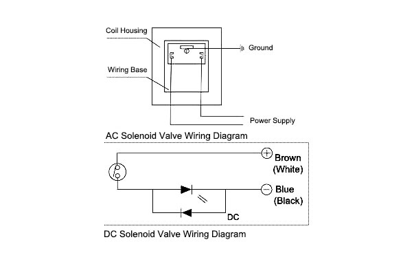
The power line of the solenoid valve can be divided into three kinds including ground wire anode and cathode. This illustrates which wires to connect for either 120 208 or 240 volt operation. Solenoid valves with four-wire dual voltage coils have a wiring diagram decal Figure 3 on the coil housing or bracket.
This illustrates which wires to connect for either 120 208 or 240 volt operation. Red red and greenyellow striped. Solenoid Valve Wiring Connection For Android Apk Download.
Asco Solenoid Valve 8262 Wiring Diagram 120v Transformer Wiring Diagram Auto Electrical Wiring Diagram Asco 8327 Wiring Diagram Online Wiring Diagram Exhaust Brakes Dodge 5 9l Cummins 2004 5 2007 Xdp Solenoid Valves Asco Redhat General Service Miniature Process Exhaust Brakes Dodge 5 9l Cummins 2004 5 2007 Xdp. Any position by loosening the coil hexscrew. ASCO Red-Hat and Red Hat IIO solenoid valves for the control of fluids are valve from the electrical energy spent in the coil or simply from the air around it.
Symbols are electrical representation only. Wiring wiring must comply with local codes and the national. The force needed to open the valve is proportional to the orifice size and fluid pressure.
And it has two wires. The output digital of my PIC will go to control a device called a Solenoid Valve this solenoid valve functions with 12 V. ASCO Series 8210 2-Way Solenoid Valve 8210G009 1206011050.
LIQ LINE SOLENOID VALVE LOW PRESSURE SWITCH OUTDOOR FAN MOTOR START CAPICATOR START RELAY START THERMISTOR CAUTION BLK or RED CH. The valve will operate at pressures from 0 psi to its rated maximum. First I want to say thank you for the help with the first part of my project.
On all the time. Pilot Operated Superwinch Solenoid Ford 8210 Asco 8290 Diagram Database Red Hat 8290 Wiring Npt Wiring 101 Catalog Diagram Ford Stainless Steel Redhat Asco 8314 Stereo Wiring Normally Closed. Volt-ampere ratings are based on inrush currents.
2 Wiring Diagram Model size 2--12 -- 5 tons 208230--3 and Model size 3 -- 5 tons 4603. When the solenoid is energized the core directly opens the orifice of a Normally Closed valve or closes the orifice in a Normally Open valve. Following colored lead wires.
Follow the wiring instructions included with the new solenoid.

45 Inspirational Honeywell Switching Relay Wiring Diagram Honeywell Wiring Diagram Relay

Diagram Starter Solenoid Wiring Diagram With Attached Solenoid Full Version Hd Quality Attached Solenoid Diagramman Prolococusanese It
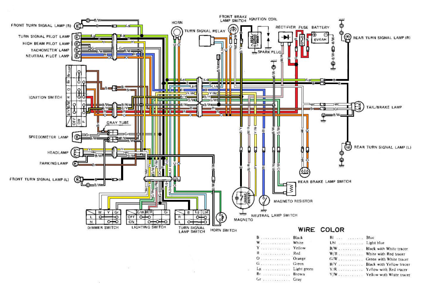
Diagram Suzuki Ts 125 X Wiring Diagram Full Version Hd Quality Wiring Diagram Diagramman Prolococusanese It

Diagram Relay Wiring Diagram Atv Full Version Hd Quality Diagram Atv Diagramman Prolococusanese It
How To Wire A Solenoid Valve
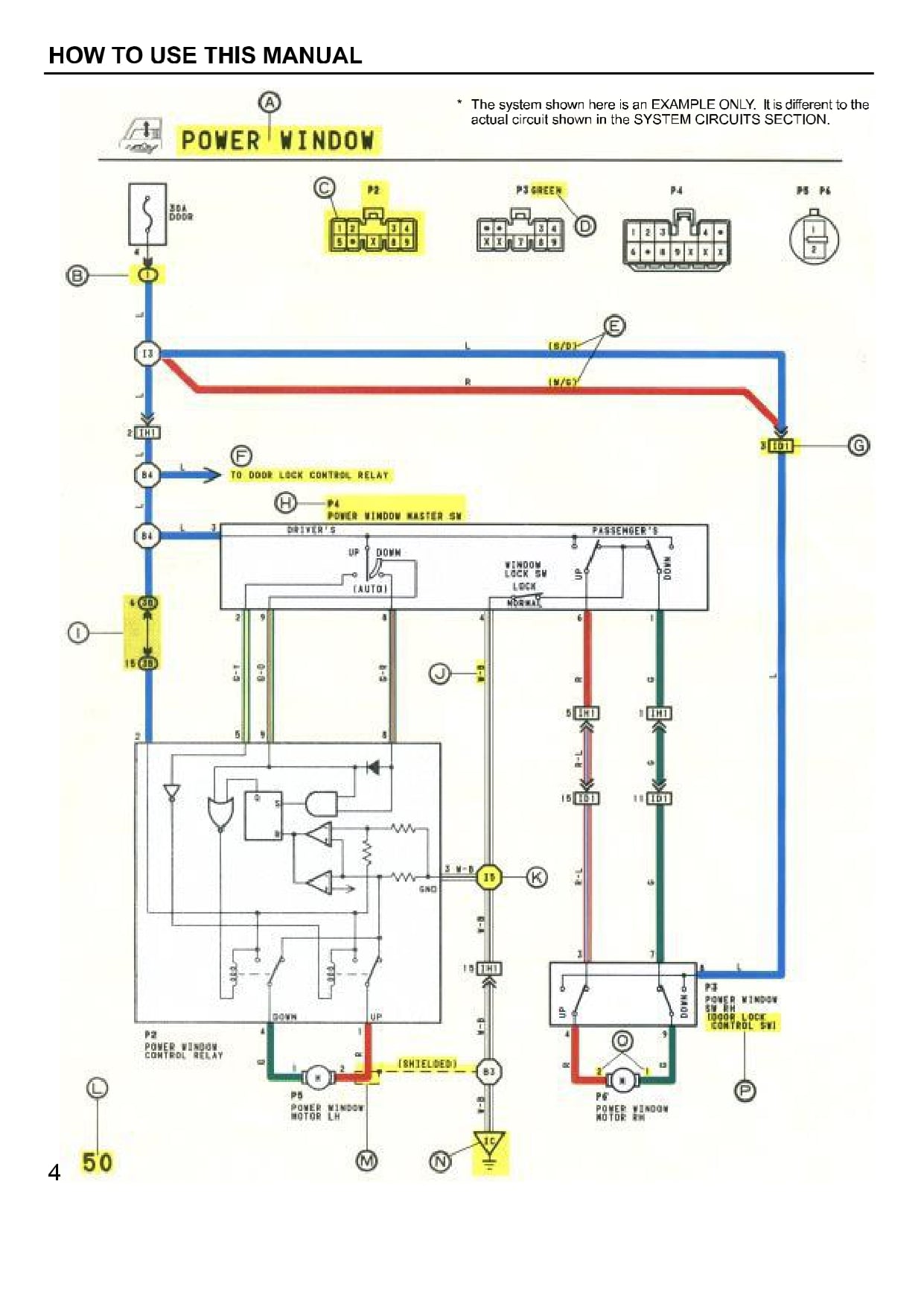
Diagram 2007 Camry Wiring Diagram Full Version Hd Quality Wiring Diagram Diagramman Prolococusanese It

Dump Trailer Wiring Diagram Submersible Pump Well Pump Wiring Diagram

16 Simple Diesel Engine Wiring Diagram Engine Diagram Wiringg Net Electrical Circuit Diagram Plugs Engine Control Unit
Diagram 120 240 Generator Wiring Diagram Full Version Hd Quality Wiring Diagram Diagramrt Teatrodelloppresso It


Diagram Wiring Diagram 120v Full Version Hd Quality Diagram 120v Diagrammar Prolococusanese It
Wiring Diagram Ecu 2kd Ftv Throttle Systems Engineering Wiring Diagram Systems Engineering Ecu

Hydraulic Solenoid Valve Wiring Diagram Volovets Info Wiring Diagram Diagram Hydraulic Systems

Diagram Dayton Capacitor Start Wiring Diagrams Full Version Hd Quality Wiring Diagrams Imdiagram Giardinowow It

70 Lovely Single Phase Magnetic Starter Wiring Diagram Electrical Wiring Diagram Air Compressor Pressure Switch Wiring Diagram

15 Ac Electrical Wiring Diagram Ac Wiring Electrical Wiring Diagram Split Ac

Diagrama De Circuito De Tierra Impresionante Diagrama De Cableado De 110 Diagrama De Cableado De Magne Wiring Diagram Norcold Refrigerator Dometic Refrigerator
![]()
Solenoid Valve Wiring

Wiring Diagram 12 Volt Relay 5 Pin 7 For Relays On 12 Volt Relay Wiring Diagram Relay Diagram Design Three Way Switch

70 Lovely Idec Relay Wiring Diagram Wiring Diagram Relay Ladder Logic