Leviton Mzd20 102 Wiring Diagram
For help with miniZ Dimming Power-Pack from Leviton. The black and white that you see are both used.

Leviton Irc How To Wire A Power Pack Youtube
Green or bare copper wall box wire Ground to Green screw.
Leviton mzd20 102 wiring diagram. Secure each connector with electrical tape. Loop wires clockwise 34 turn around terminal screws. Black dimmer lead to Line Hot wall box wire removed from.
Roll over to zoom. 0 10 VDC ZONE 1 MZD20-102 MZD20-C02 W V B G W V G BK W B R w B LINE VOLTAGE WIRING 2 ZONE MODEL. You cannot replace the switch with a switchreceptacle combo because there is no neutral wire.
Green dimmer Ground lead to Green or bare copper wire in wall box. Lighting Lighting Controls Lighting Control Systems - Wired Room Controllers. Equal to Leviton 1081 toggle OR Leviton 56081 Decora LVT Low voltage switch maintained Equal to Leviton 12021-2 toggle or Leviton 56021-2 Decora.
This video explains how to wire a Leviton ODC0P-00W photocell to a Leviton Integrated Room Controller IRC. Insert wires through the hole in the included washer then place the included washer over the rod and screw on the included hex nut. Screw wire nuts on clockwise making sure no bare conductors show below the wire connectors.
Connect wires per WIRING DIAGRAM as follows. Green or bare copper wire in wall box to timer switch. Leviton mZd20-102 Manuals User Guides.
Black wall box wire LINE 1 - HOT to Brass screw Common. For additional switching capacity up to 50 ballast use dimmers in conjuction with a Leviton ODP 120277V Power Pack. To all installed remotes cannot exceed 300 ft 90Black m.
Integrated Room Control IRC Engineered to deliver a simple and cost-effective California Title 24 2013 2012 IECC and ASHRAE 901 energy code compliant solution the Leviton IRC features high performance lighting control capabilities in a single easy to install compact device. Leviton 5625 Wiring Diagram. Violet 22 AWG Signal.
Leviton mZb00-102 Quick Start Manual. Green dimmer Ground lead to Green or bare copper wire in wall box. Gray 22 AWG Alternate 0-10Vdc Control Loop Route LoadR ZoneV 2 IRC Color.
This version of Leviton mZb00-102 Manual compatible with such list of devices as. Twist strands of each lead tightly and with circuit conductors push firmly into appropriate wire connector. I can get the light to work with the switch but the receptacle will not operate anything I plug into it.
Pilot light is ON when switch is ON. Connect wires per WIRING DIAGRAM as follows. Black wall box wire LINE 2 -.
Single-Pole Wiring Application using 3-Way Dimmer Cat. MZD20-102 IRC Dimming Version 2 zone 2 relay 120V277VAC Title 24 compliant ASHRAE 901 compliant The Leviton Integrated Room Control IRC combines single room occupancy sensing daylight harvesting 0-10V dimming Partial ON Partial OFF and demand response. MZd22-102 mZd22-C02 mZd30-C01 mZn20-C02 mZn22-102.
11 UL924 Bypass GreenMAX 0-10V 4-Wire Dimmed Load 12 UL924 Bypass 0-10V 4-Wire Sector Relay Dimmed Load 13 UL924 Bypass Provolt Auto-ONOFF Manual-ONOFF. The timer switch must be installed in a wall box that has a Line Hot connection. For direct load application configurations wiring diagrams 1 2 and 3 refer to table 1 and table 2 for ballast information.
The Leviton Integrated Room Control IRC combines single room occupancy sensing daylight harvesting 0-10V dimming Partial ON Partial OFF and demand response capabilities into a single easily installed package. Connect wires per WIRING DIAGRAM as follows. Screw wire nuts on clockwise making sure no bare conductors show below the wire connectors.
This video explains how to wire a Leviton occupancy sensor power pack and a Leviton marked controlled receptacle to a Leviton Integrated Room Controller IRC. Connect low-Voltage wires from Power Pack to Sensor per WIRING DIAGRAM as follows. Green or bare copper wall box wire Ground.
COMMON FEED Single Line Hot Single pole switch controls lights. Quick start manual Operation users manual. Maximum wire length from timer switchIdentifying your wiring application most common.
IRC Dimming Version 3 zone 1 relay 120V277VAC Title 24 compliant ASHRAE 901 compliant. Connect wires per WIRING DIAGRAM as follows. User Manuals Guides and Specifications for your Leviton mZd20-102 Other.
MZD20-102-Multi-Tech Ceiling Mount Occupancy Sensor OSC20-RMW Photocell ODC0P-00W Low Voltage 4-Button Switch White RLVSW-4LW OPP20 Super Duty Power Pack OPP20-RD4 ROOM-IN-A-BOX KITS - order a complete system with one part number. Database contains 2 Leviton mZd20-102 Manuals available for free online viewing or downloading in PDF. Engineered to deliver a simple and cost-effectiv.
Secure each connector with electrical tape. Step 4 Connect wires per WIRING DIAGRAM as follows. Click Add to Cart to buy Leviton MZD20-102 miniZ Dimming Power-PackAlso known as.
Loop wires clockwise 34 turn around terminal screws.
Https Www Leviton Com En Docs Applications Cookbook Iecc Pdf
Https Www Leviton Com En Docs Applications Cookbook Iecc Pdf
Parking Garage Basic Lighting Controls

Hallway Advanced Lighting Controls
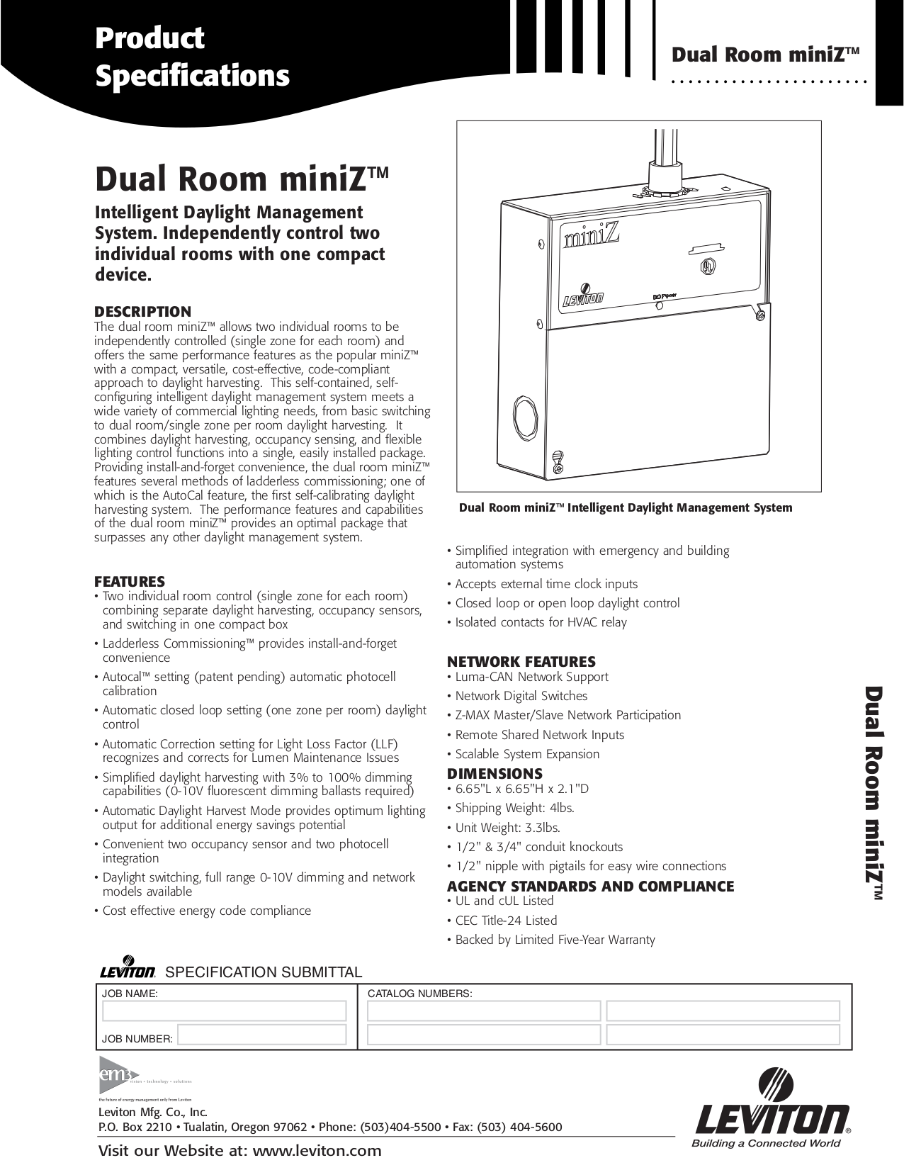
Pdf Manual For Leviton Other Miniz Mzd20 102 Harvesting Controller
Https Www Leviton Com En Docs Applications Cookbook Iecc Pdf

Leviton Irc How To Wire A Digital Switch Youtube
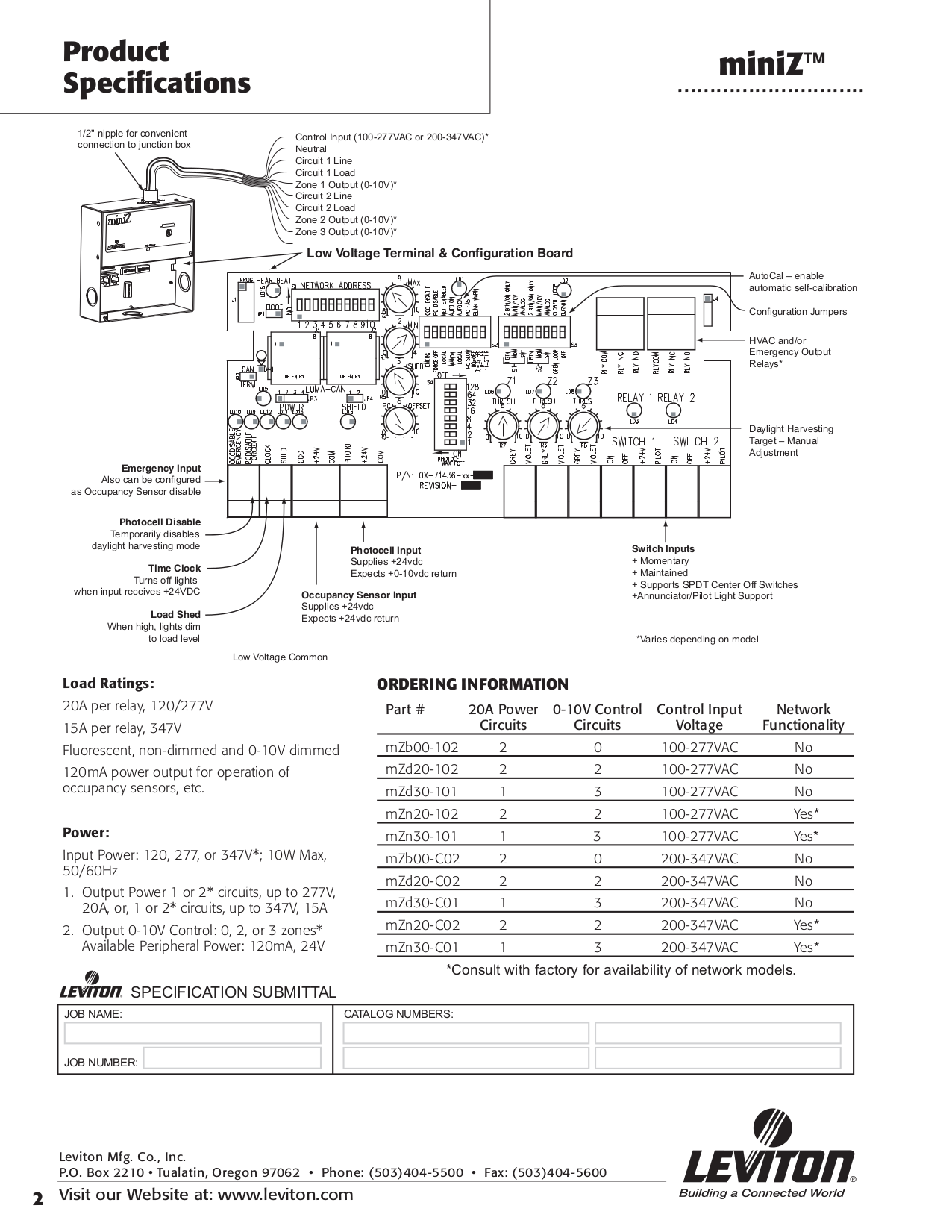
Pdf Manual For Leviton Other Miniz Mzd20 102 Harvesting Controller
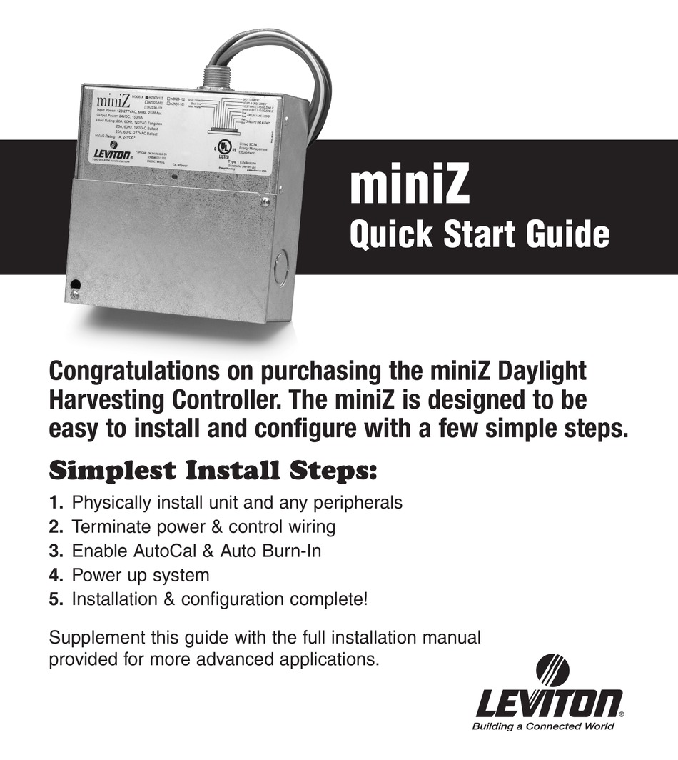
Leviton Miniz Mzb00 102 Quick Start Manual Pdf Download Manualslib
Integrated Room Control Irc Single Zone 2015 Leviton 2012 Iecc For Lighting Controls
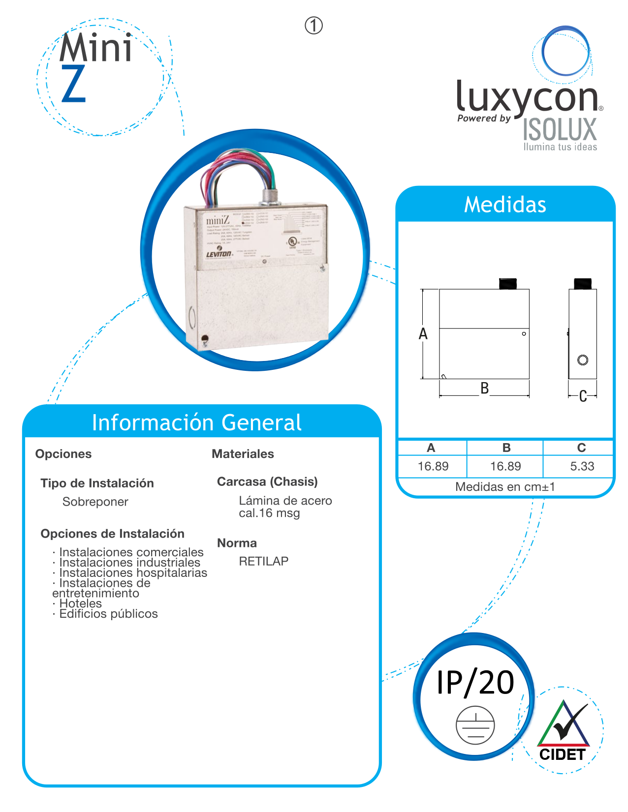
Pdf Manual For Leviton Other Miniz Mzd20 102 Harvesting Controller
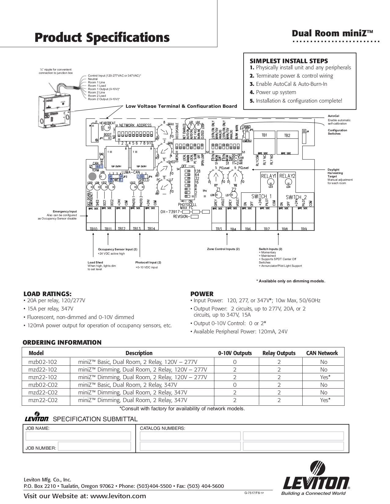
Pdf Manual For Leviton Other Miniz Mzd20 102 Harvesting Controller

Pdf Manual For Leviton Other Miniz Mzd20 102 Harvesting Controller

Small Office Basic Lighting Controls

Cec Title Ron France Leviton Introducing The Leviton T24 Design Guide Ppt Download


