Zener Barrier Wiring Diagram
Each channel contains two stages of pulse-tested Zener or forward-connected diodes and an infallible terminating resistor. Type ET-7018 - Connections and type of Zener barrier according to wiring diagram 1207240001 3.

How Zener Barriers Work
Power supply Removable terminals black Removable terminals blue Switch S1 Mode of operation channel I Switch S2 Mode of operation channel II.
Zener barrier wiring diagram. Relay output I LED red. For Exia the Zener barrier has to be safe with two faults so the safety components have to be assessed to ensure they cannot fail unsafe. A resistor at least two zener diodes and a fuseThe resistor limits the current to a specific value known as the short circuit current IscThe zener diode limits the voltage to a value referred to as open circuit.
A Zener barrier is an associated equipment that is installed in the safe area. Connection via Zener barrier. The basic diagram of Zener diode as voltage regulator is given below To fix the current through this diode series resistance R is introduced whose value can be chosen from the following equation.
The Zener barrier is usually designed for zone 0 connectivity Exia and can then be used for zone 1 Exib and zone 2 Exic. Cable length between probe and signal processing unit 200m 656 ft - Cable for the connecting the probe to the Zener barrier. Depending on the application increased or decreased intrinsic safety parameters apply for serial or parallel connection.
Check the wiring between resistor - PCB and appropriate zener barrier. The Zener Barrier has a positive polarity i. For the detailed parameters refer to the Zener Barrier certificate.
Relay output II LED red. The Zener Barrier can be used for both alternating voltage signals and direct voltage signals. An IS barrier should only supply and IS field device such as a suitably certified IS sensor or a suitable simple apparatus.
Measure the voltage between terminal nos. A suitable procedure is described in the EN 60079-25. Resistor value ohms V1 V2 Zener current load current.
This is achieved by duplication Zener. It is designed to limit the amount of energy that could appear in an electrical circuit passes through the hazardous area despite the connection before the barrier. It is not allowed to apply the ignition diagrams acc.
The diodes of diode return prevent a current into the hazardous area therefore the current assumption for intrinsic safety calculations is zero. Zener Barrier Wiring Diagram DC. Wiring Diagram 1 3 4 6 2 5 13 15 12 9 10 7 14 11 8 1 2 OUT CHK PWR S2 S1 S3 I II Front view LED yellow.
Power Supply 1 2 Red Black White 3 2 3 2 1 Output 5 VDC Input Voltage Versions WARNING The nature of the sensor is that it is a non-voltage producing device con-taining no energy-storing components. Interconnection of Safety Barriers Polarity - -. Power Supply 1 2 Red Black White 3 2 3 2 1 Output 10-22 VDC Input Voltage Versions WARNING The nature of the sensor is that it is a non-voltage producing device con-taining no energy-storing components.
LBSC channel I LED yellow. Z 788H for analog current output Hazardous Area Safe Area Power Supply Negative Important. The simple circuit diagram is displayed below where the transistor is being used as emitter follower.
The way out of it is to use a zener diode circuit with a seris pass-transistor. Check the wiring between resistor - zener barrier and detector interface module. Wiring Diagram 1207240001 page 1 of 2 _____ 02282002 a Wiring with Zener barrier Pepperl Fuchs Mod.
However since its primary use is in. Circuit diagram for an intrinsically safe barrier is shown in Figure 2. Z 722 for digital current output b Wiring with Zener barrier Pepperl Fuchs Mod.
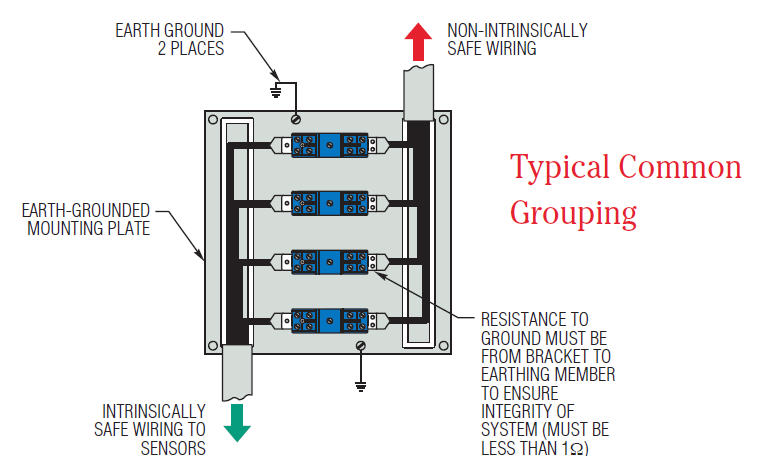
They can be installed in Class I Division 2 and Zone 2 hazardous areas when installed in enclosures with the appropriate protection category. Figure 1 - Bulletin 937 Zener Barrier System Mounting The 937 barriers snap on standard 35 mm DIN rail and are ideal for racks or control cabinets. In the event of an electrical fault in the safe area the diodes limit the voltage that can reach the hazardous area and the resistor limits the current.
Connect signal lines to the screw terminals at both sides of the barrier 1 and 2 andor 5 and 6 at the safe-area side 3 and 4 andor 7 and 8 at the hazardous-area side. Also the combination of an IS barrier and an IS field apparatus should be carefully looked at with for example the standards EN 60079-25 and EN 60079. Positive single-channel Zener Barrier with negative ground.
Figure 2 - Mounting the Zener Barrier. Zener Barrier Wiring Diagram DC. Zener diode circuit for a simple regulated power supply.
LBSC channel II Switch S3 LBSC-monitoring LED green. However since its primary use is in. Resistors to limit the current.
To EN 60079-11 for the assersment of the intrinsic safety in case that safety barriers with electronic current limitations need to be interconnected. All MTL7700 range barriers are based on the same simple principle. The anodes of the zener diodes are grounded.
The above shown simple Shunt regulator is not mostly effective and not feasible for higher current applicationz. Instrumentation that produces an output signal conditioners usually requires two barriers one for each. Start up The ROTRONIC probes are adjusted and tested at the factory.
A barrier consists of. The Zener Barrier is for evaluation of signals from the hazardous area. There are three components to a barrier that limit current and voltage.
You should not supply an Ex d piece of equipment with an IS barrier. For most non-voltage-producing devices located in a hazardous area a single Zener Barrier that is negative-earth-ground can be used for intrinsic safety. The safe-area terminal 1 is also used as a power connection when power is provided from the safe area see section 522 for details.
3418 and between terminal nos. 3618 at the detector interface module.
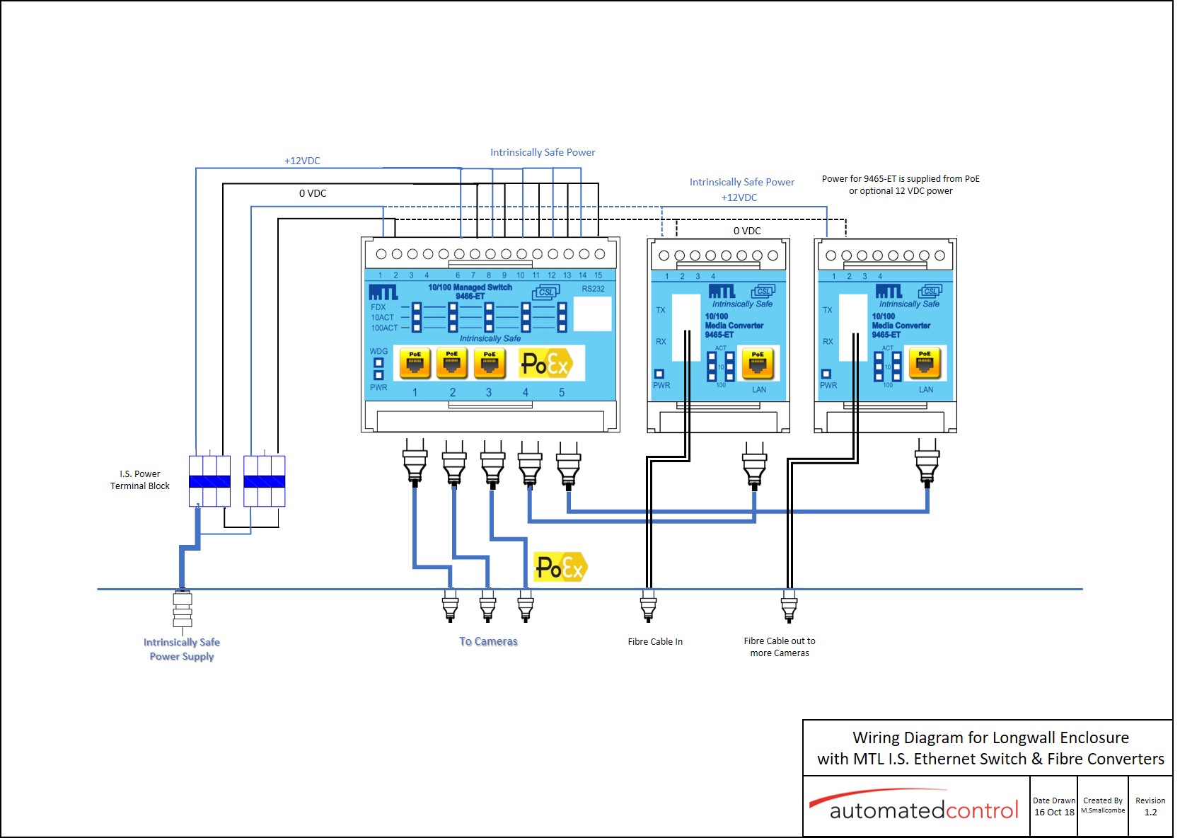
Intrinsically Safe Ethernet Media Marshalling Enclosure Ip66 Demo Automated Control
Http Literature Rockwellautomation Com Idc Groups Literature Documents Td 937 Td003 En P Pdf
How Zener Barriers Work

Extech Hazardous Area Specialist Products Supplier
Relays And Barriers Maintenance Gems Sensors
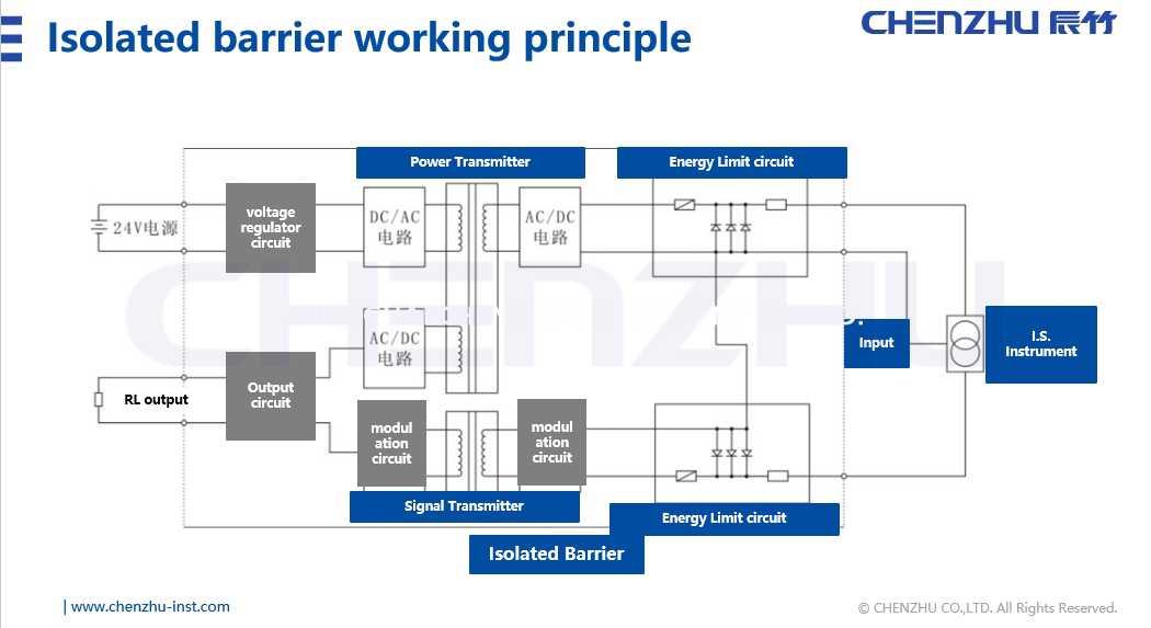
Does Isolated Barrier Require Grounding Like Zener Barrier

Extech Hazardous Area Specialist Products Supplier
Http Literature Rockwellautomation Com Idc Groups Literature Documents Td 937 Td003 En P Pdf

The Basics Of An Intrinsic Safety Barrier

13 Zener Barriers Operating Instructions Application Examples Hazardous Area Safe Area Vega Z728 Zener Barriers User Manual Page 13 23

Zener Diode Barrier Principle Instrumentation Tools

Intrinsic Safety Explosion Proof Barrier Zener Barrier For Transducer Series Valcom Co Ltd Specialized Manufacturer Of Digital Pressure Meters And Load Cells
Http Literature Rockwellautomation Com Idc Groups Literature Documents Td 937 Td003 En P Pdf
Https Www Tandfonline Com Doi Pdf 10 1080 20464177 2009 11020219
Intrinsically Safe Explosion Proof For Pressure Sensor Zener Barrier Series Valcom Co Ltd Specialized Manufacturer Of Digital Pressure Meters And Load Cells

Zener Diode Barrier Principle Instrumentation Tools

How To Design An Intrinsically Safe System Awc Inc

How Zener Barriers Work
Http Literature Rockwellautomation Com Idc Groups Literature Documents Td 937 Td003 En P Pdf