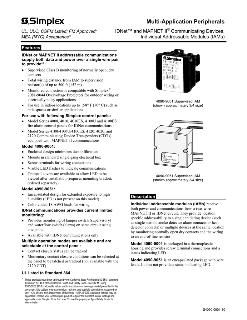
Simplex Iam Wiring Diagram
Tamper Switch with IDNET IAM Figure 2 Notes. Loosen the two screws on the square back box.
Simplex 4090 9002 Iam Relay Idnet Assembly
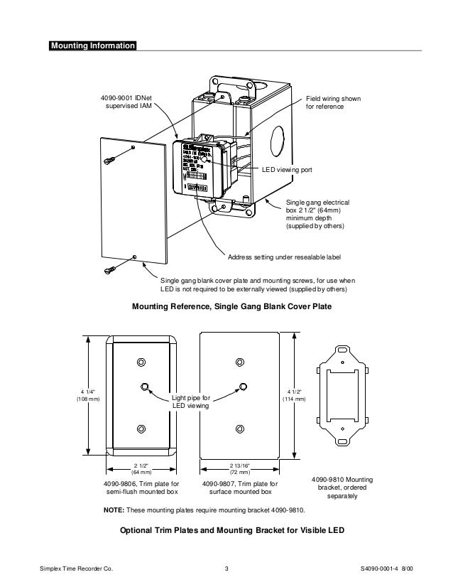
Mount the IAM to the back box using the teardrop holes on the mounting bracket.
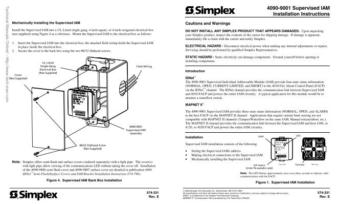
Simplex iam wiring diagram. Insert the Supervised IAM into the electrical box. Table 1 TB1 Terminations Position Label Description TB1-1 ADDR LOOP IDNet input pass-through if required TB1-2-ADDR LOOP -IDNet input pass-through if required. Up to 10000 ft 3048 m total wiring distance including T taps.
Wire peripherals in accordance with the appropriate 4100 Field Wiring Diagram 841-731. The attached field wiring holds the Supervised IAM in place inside the electrical box. The IDNet SLC also is shown with short circuit isolation devices.
The IDNet module is specially designed for retrofit installations when existing wiring is to be re-used. Interconnecting wire routes may. To mount in a 4 1116 square back box order Adapter Plate.
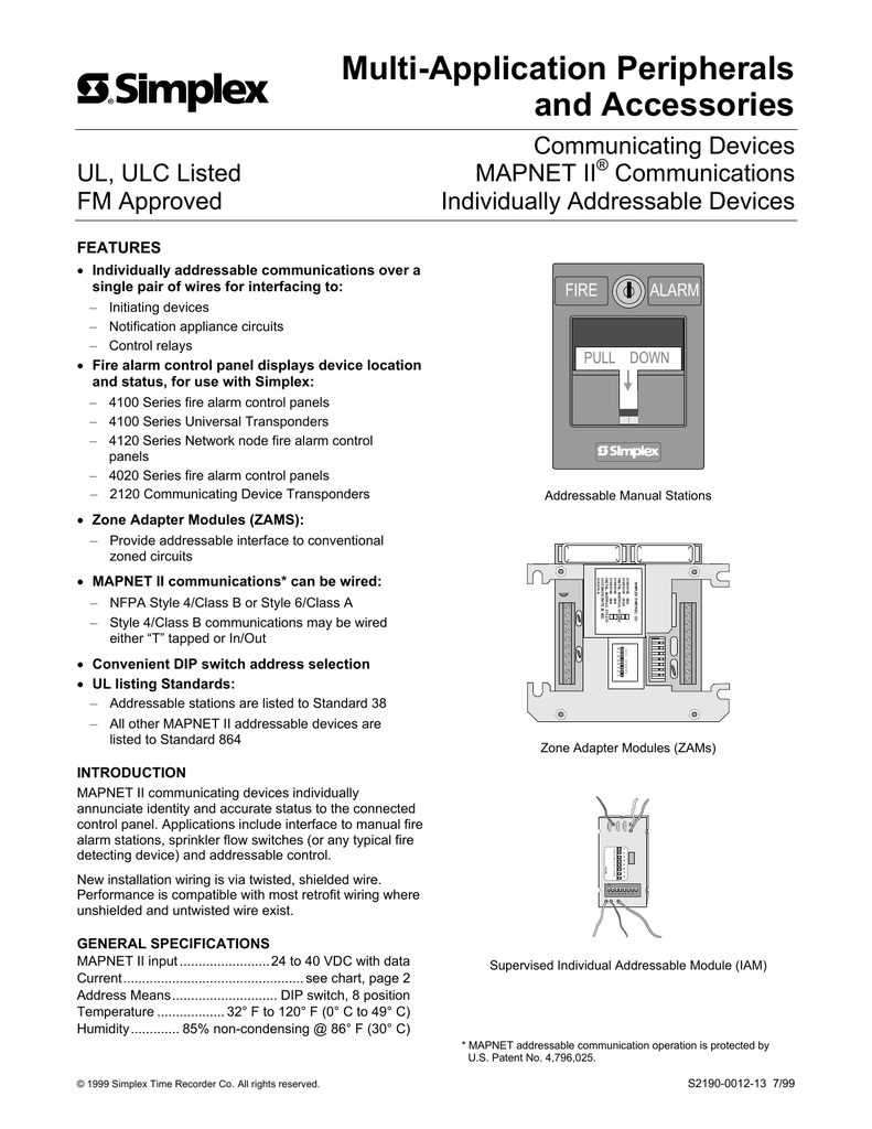
Wire a MAPNET II device in accordance with the appropriate MAPNET II Field Wiring Diagram 841-804. A MODEL Typical Supervised IAM Wiring Diagrams MAPNET II. Refer to Field Wiring Diagram 842-073 for further information on wiring Supervised IAMs to IDNet.
Ignition wiring diagram available simplex 4100 installation manual wiring diagram installation 1 anchor the smart pump to concrete pad using mounting holes provided in the base part of typical wiring diagram. Built-in Quad Isolator uses IDNet addresses 247 to 250 Supports 246 external addressable IDNet devices Improved noise immunity eliminates the need for shielded and twisted wire in most applications. Resistors other than those described above will be used by the Simplex Technical Representative TR during installation checkout.
Maximum wire length is 400 feet 18 AWG. For Class A wiring it is recommended that isolators be located as the first and last devices in the loop as shown below in figure 5. Architectural wiring diagrams discharge duty the approximate locations and interconnections of receptacles lighting and unshakable electrical facilities in a building.
Use the following two pages to wire the Signal IAM. Simplex offers semi-flush and surface covers ordered separately with a light pipe. TCA Simplexs 2.
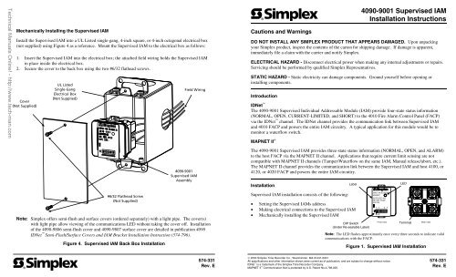
Mount the Supervised IAM to the electrical box as follows. Refer to Field Wiring Diagrams 841-804 or 841-996 for further information on wiring Supervised IAMs to MAPNET II. Loosen the two screws on the square back box.
Field installed wires maintain polarity and use 12 to 18 AWG wire from supervised IAM assembly to system power supply. Wire Connections Screw terminals for inout wiring 18 to 14 AWG wire 082 to 208 mm2 IDNet or MAPNET II Communications Wiring Reference Up to 2500 ft 762 m from control panel Up to 10000 ft 3048 m total wiring distance including T-Taps Compatible with Simplex 2081-9044 Overvoltage Protectors Dimensions. All terminal blocks accept 12-18 AWG wire.
Some key features include. IDNet and MAPNET II wiring are supervised and power-limited. 841-804 for MAPNET II operation Wiring Distances Distance from IAM to Contacts 500 ft 152 m maximum without protectors 400 ft 122 m maximum with 2081-9044 Overvoltage Protectors Wiring Distance Reference per.
Relay IAM with T-Sense 18 k 12 W Maximum distance to contacts is 500 ft 152 m input is for indoor wiring only IDNet Wiring Distances. Install the Relay IAM into a UL Listed 4-inch back box not supplied using Figure 4 as a reference. Wiring Procedure Refer to Figure 2 and the notes for wiring instructions.
Tamper switch harness and 68K resistor are factory-connected to locations 3 and 4 on the. Up to 2500 ft 762 m from host control panel. Figure 5 is a modification of Figure 4Each floor is wired as a Class A Style 6 connection.
Field Wiring Diagrams 842-073 for IDNet operation. Mount the IAM to the back box using the teardrop holes on the mounting bracket. IDNet Relay IAM.
Mount the IAM to the back box as follows. V EP IDNet INDIVIDUAL ADDRESSABLE MODULE RELAY IAM. This reference wiring diagram shows a Class A signal riser providing input to each Signal IAM and a Class A IDNet signaling line circuit SLC for control of the Signal IAMs.
Secure the IAM to the back box using the two 832 panhead screws. The Signal IAM provides two terminal blocks which are described in Tables 1 and 2 below. -SIMPLEX OLD STYLE IAM MAPNET II ADDRESSABLE MODULE.
SUPERVISED IAM TYPICAL SUPERVISED IAM WIRING DIAGRAMS. Mount the 8 Amp Relay IAM into a UL Listed 4-inch back box as follows. Simplex Wiring Diagram Apartment Wiring Diagrams.
Secure the cover to the back box using the two 632 flathead screws. Simplex fire alarm nys price list. These diagrams show the wiring for particular modules or cards or detector bases which Simplex Fire Alarm systems.
Simplex Speaker Making sure you have the right parts for your Simplex devices is always a good idea which is why we offer a wide range of products to choose from. Simplex iam module wiring diagram as well as simplex manual pull station wiring together with simplex clock wiring furthermore simplex clock. Refer to Installation Instructions 574-874 for detailed installation information--.
4090-9116 Addressable IDNet Isolator Installation Instructions 5 Class A Wiring. A wiring diagram is often used to troubleshoot problems and to make determined that every the contacts have been made and that whatever is present. Secure the IAM to the back box using the two 832 panhead screws.
Wiring Information Refer to reference diagrams on pages 3 and 4 Wire Connections Screw terminals for inout wiring 18 to 12 AWG wire Address Means DIP switch 8 position Temperature Range 32 F to 120 F 0 C to 49 C intended for indoor operation Humidity Range Up to 85 RH at 86 F 30 C. Signal Riser wiring is inout no T-tapping is allowed.
Blogmaygomes Simplex Fire Alarm System Wiring Diagram
Https Tycosafetyproducts Anz Com Public Datasheet S4090 0001 2 Pdf
Blogmaygomes Simplex Fire Alarm System Wiring Diagram

4090 9001 Supervised Iam Installation Instructions Alarm Device

Simplex 4010 Spectralert Mdl Module Help Fire Alarm Help The Fire Panel Forums
4090 9002 Control Module Relay Electrical Wiring
Mapnet Ii Addressable Fire Alarm Systems
Http Interamsa Com Downloads Instalacion 4090 9101 Pdf
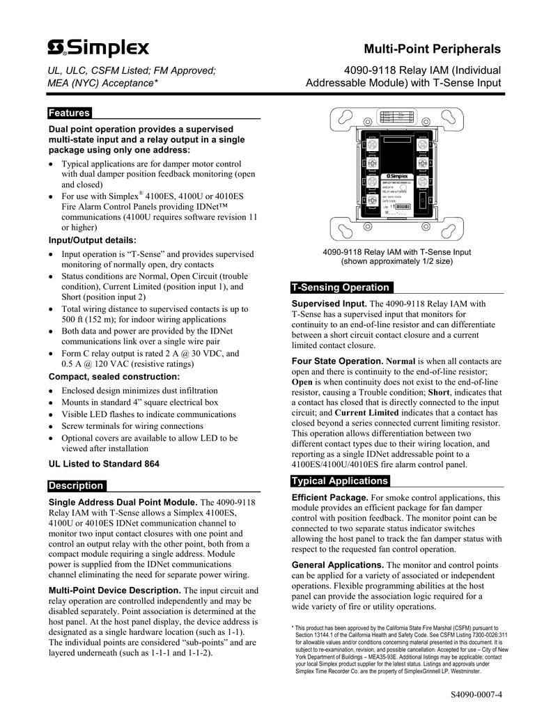
S4090 0007 4 7 11 4090 9118 4090 9118 Relay Iam Individual Addressable Module With T Manualzz

Simplex Idnet 4090 9002 Installation Instructions Pdf Download Manualslib

4090 9101 9106 Monitor Zams Installation Instructions Manualzz
4090 9001 Supervised Iam Installation Instructions Alarm Device

