Gps Tracker Wiring Diagram Pdf
It can also be connected to the siren you buy with the tracker. DO NOT PLUG THE POWER CABLE INTO THE VTU AT THIS TIME.

Dc Ammeter Shunt Wiring Diagram L Fd8e3c77ca6fd112 Gif 1479 786 Wiring Diagram Car Amplifier Diagram
Once thats done connect the Red wire to the vehicles power.

Gps tracker wiring diagram pdf. The GPS devices require a 12 VDC Constant RED Wire and solid chassis ground BLACK Wire. This user manual will help you operate the device efficiently and correctly and allow you to start using your GPS tracker as quickly as possible. This connection serves as a ground for the device.
Connect the CommandGPS Black Wire to your vehicles chassis. Connect the AwareGPS black wire to your vehicles chassis. Locate the vehicles ignition wire reference the vehicles wiring diagram in order to locate.
The TTU-28x0 is a rugged IP66 rated enclosure incorporating a processor a GPS receiver a wireless data modem and a vehicle-rated power supply. Siren is Option 616 Knowing about the type of t he door trigger is positive or ne gative trigger. It can also be connected to the siren you buy with the tracker.
Strip the Black Wire on the Linxup GPS device. The CalAmp LMU-26xx is an integrated CellularGPS communications device for use in-vehicle tracking. The tracker is waterproof but please still avoids the long-term placement in the places of water infiltration.
How to easily program and setup the tracker for best results. Verify the ignition wire by measuring the operating voltage while the key is turned to the ON or START position the. Verify the Ignition Wire by.
If it is different with its exact current location pay attention to check the. Is marked by a sticker on the VTU showing GPS THIS SIDE UP. There are various reasons why you might want to install a GPS tracking device on your vehicleTwo of the main reasons are to improve a vehicles security and to be able to locate it 247By installing a tracking device the chances of recovering a stolen vehicle increase tremendously with the help of real-time location tracking.
Connect the wires according to the following table. This connection serves as a ground for the device. Strip the Black Wire on the device.
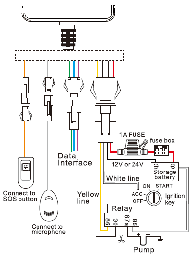
The orange wire can be connected to the original car alarm horn. And longitude is the position that the tracker received GPS signals at last. Install the device in your vehicle connect the wiring harness to the base unit as indicated in the diagram above.
Connect the Linxup Black Wire to your vehicles chassis. This connection serves as a ground for the device. The orange wire can be connected to the original car horn.
Locate the vehicles ignition wire reference the vehicles wiring diagram in order to locate. A wiring diagram is a simplified traditional photographic representation of an electric circuit. Locate the vehicles ignition wire reference the vehicles wiring diagram in order to locate.
Verify the Ignition Wire by measuring the operating voltage while the key is. Connect the White wire to the vehicles ignition or accessory power. Connect the Wires to the Vehicle - Use the wiring harness provided with the installation kit.
See Wiring Diagram for details 4. Connect the device Black Wire to your vehicles chassis. The CalAmp TTU-28x0 is a motorized asset tracking and communications device that resides in private commercial or government vehicles.
Use a multi-meter to. It reveals the elements of the circuit as streamlined forms as well as the power and signal connections in between the gadgets. Built-in GPS and GSM antenna external antenna can be optional.
Locate the vehicles ignition wire reference the vehicles wiring diagram in order to locate. 44 Device wiring diagram. Apart from anti-theft purposes businesses use GPS tracking.
The IP address and port of Communication Protocol in the tracker can be modified and transferred data to other platformSendSMS ipipaddressportportnumber totheunitIfthetrackersIPaddressandport. It is installed within the vehicle in order to provide this information and is wired into. Cautions of device wiring 51 PowerACCTele-cutoff petrolelectricity control line 4.
This connection serves as a ground for the device. 7 GND Black Ground wire 8 MOTOR Yellow Connect to relay control line 9 ACC Orange Connect to ACC ignition. Wiring diagram 615 Note.
GPS Vehicle tracker GPSGSMSMSGPRS User Manual. Optional Connections - Connect GREEN input. This connection serves as a ground for the device.
Strip the Black Wire on the device. If you need an external power supply cut oil power system and SOS feature please find 4PIN main wire wiring diagram as. Locate the vehicles ignition wire reference the vehicles wiring diagram in order to locate.
TK102 Mini GPS Tracker User Manual Version 12 Introduction Thank you for purchasing the iTrack TK102 Mini GPS Tracker. Connect the Black wire to Ground. Make sure to read this manualcarefullybefore using this productsoas to avoid delays orconfusion with its.
Collection of gps tracker wiring diagram. Connect the device Black Wire to your vehicles chassis. It provides communications for vehicle position and operating information as part of an overall vehicle tracking solution.
The constant 12 Volt power source wire is usually located in the ignition switch harness. Verify the Ignition Wire by measuring the operating voltage while the key is turned to the. Please make sure to read this manual carefully before using the device.
Verify the Ignition Wire by measuring the operating voltage while the key is. The is a free source on the internet to obtain Vehicle Wiring Diagrams.

Wiring Diagram For Gps Tracker
![]()
Wiring Diagram For Gps Tracker
302 Gps Tracker User Manual Shenzhen Coban Electronics

Wiring Diagram For Gps Tracker

Vehicle Tracking And Accident Alert System Using Msp430 Launchpad And Gps Module Vehicle Tracking Gps Gps Tracking

Bass Midle Treble 3 Line Crossover Active Circuit Schematic Diagram Wiring Diagram Crossover Circuit Bass

Digital Communications Solution Manual By Leon Couch Textbook Textbook Rental Solutions
Http Www Meitrack Com Cd Download Product User Guide Meitrack T366l User Guide Pdf

Coleman Pop Up C Er Wiring Diagram Wiring Forums Wiring Diagram Diagram Electric Cooker
Gt800 Vehicle Gps Tracker User Manual A A 2 Shenzhen Concox Information Technology
The Latest Gt06n Manual You Should Have Shenzhen Jimi Iot Co Ltd
Wiring Diagram For Gps Tracker

G05 Gps Tracker User Manual Coban Group Shenzhen Cantrack Technology

70 Fresh 24v Switching Relay Wiring Diagram Wiring Diagram Relay Electromagnet
Image Result For Friga Bohn Evaporator Diagram Wiring Diagram Electronics Circuit

2011 Jeep Grand Cherokee Wiring Diagram In 2021 Car Stereo Diy Car Audio Systems Diy Car Audio Installation

Diy Location Tracker Using Gsm Sim800 And Arduino Arduino Electronic Circuit Projects Electronics Circuit Diagram

How To Wire A 4 Channel Amp To 4 Speakers And A Sub Car Amplifier Car Stereo Systems Sound System Car
![]()
Wiring Diagram For Gps Tracker