1794 Tb3 Wiring Diagram
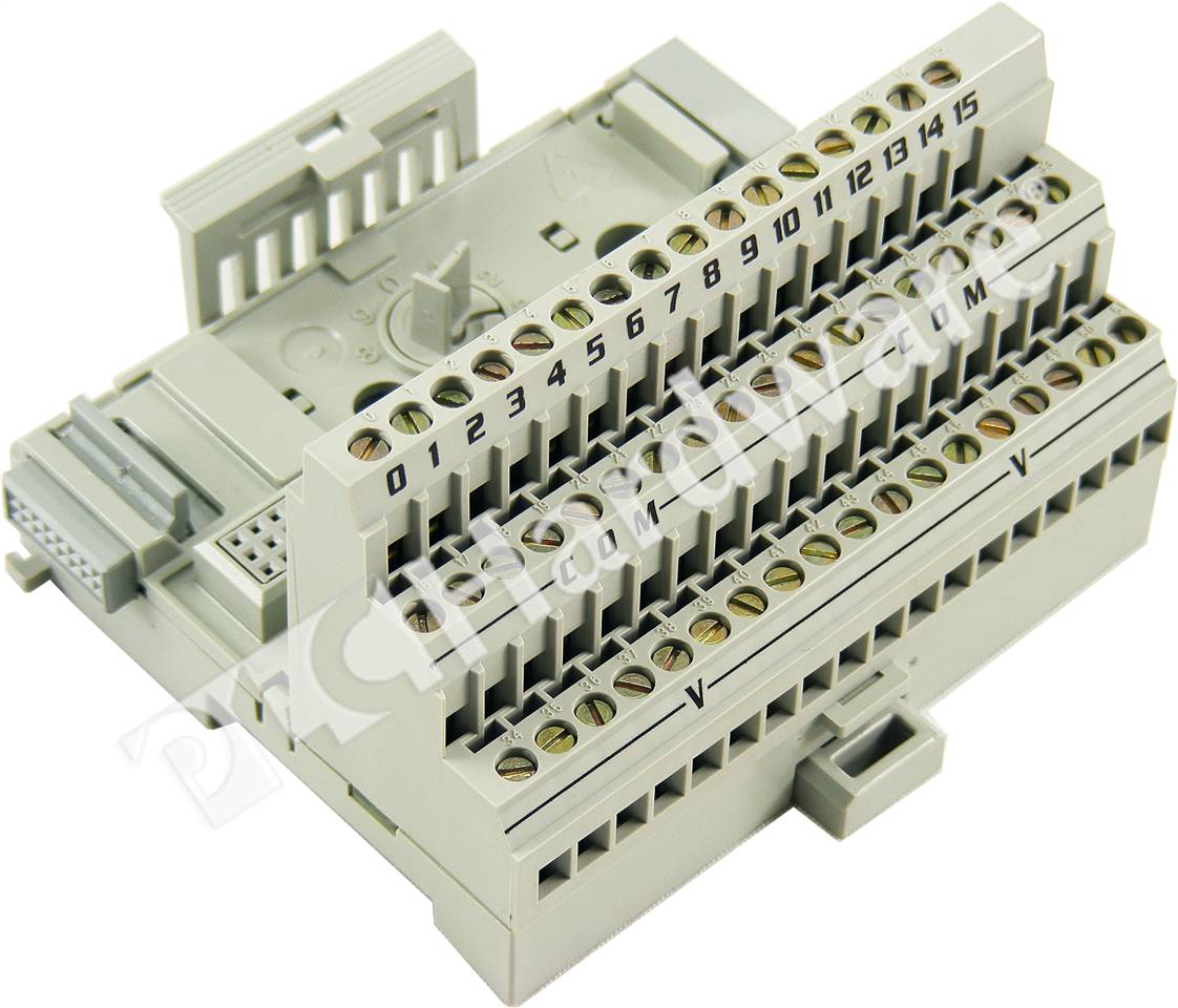
1794-TB3T -TB3TS - Terminals 34 35 50 and 51 are internally connected in the terminal base unit. V dc Power 1794-TB3 -TB3S - Terminals 34 thru 51 are internally connected in the terminal base unit.

Connect the associated V AC.

1794 tb3 wiring diagram. Isolated inputs or outputs protected outputs electronic fusing or diagnostics available on some modules. Show More Description Important Notice. 1794-TB3 3-Wire Screw Clamp Terminal Base Unit 20 1794-TB3S 3-Wire Spring Clamp Terminal Base Unit 21 1794-TB3T Temperature Terminal Base Unit 22 1794-TB3TS Spring Clamp Temperature Terminal Base Unit 24 1794-TB3G Screw Clamp Grounded Terminal Base Unit 24 1794-TB3GS Spring Clamp Grounded Terminal Base Unit 25 1794-TBN Terminal Base Unit NEMA-Style Screws 26 1794.
Connect individual input wiring to numbered terminals on the 015 row A as indicated in the following table on the next page. 1794 FLEX IO Analog Modules. Installing Your Digital InputOutput Module The 1794-IB10XOB6 module mounts on a 1794-TB3 or -TB3S terminal base.
Baca Juga
- Gps Tracker Wiring Diagram Pdf
- 05 300c Radio Wiring Diagram
- 1970 Gmc Wiring Diagram
- 1972 Chevelle Ss Wiring Diagram
- 1964 Vw Bus Wiring Diagram
- 1996 Chevy Silverado Brake Light Wiring Diagram
- 05 Sport Trac Fuel Float Wiring Diagram
- 14+ Coil Pack Wiring Harness
- 1986 Nissan 300zx Wiring Diagram
- 1968 Ford F100 Fuel Gauge Wiring Diagram
Densities range from 832 points. Other accessories manuals cables calibration data software etc. 1794-TB3T -TB3TS - Terminals 16 17 19 21 23 25 27 29 31 and 33 are internally connected in the terminal base unit.
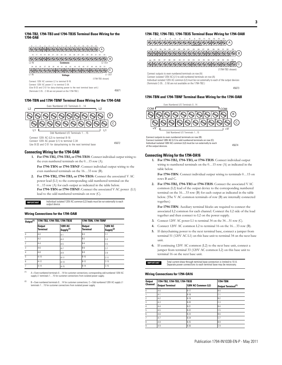
Connect individual output relay contact customer load wiring to numbered terminals on the 015 row A as indicated in the table below. Connect the associated output common to the corresponding terminal on the 1633 row B for each output as indicated in the table below. Connect individual input wiring A A- B B- Z Z- G G- for each channel to numbered terminals on the 0-15 row A as indicated in the table below.
Do not use any cleaning agents. Connect the associated V AC common L2 lead of the output device to the corresponding odd numbered terminal on the 015 row A for each output as indicated in the table below. Connect the associated V DC power lead of the input device to the.
1794-OB8EPK - even numbered terminals 0-14. The 1794-TB3 has a Flexbus rating of 5V DC at 640mA and it supplies a 2A current to the IO terminals. 1794-IF8IH 1794-OF8IH 1794-IF8IHNFXT Isolated InputOutput HART Analog Modules User Manual.
The equipment must not be used outside of this range. Publication 1794-IN019H-EN-P - January 2011 Working Voltage and Isolation Voltage Ratings Wiring to a 1794-TB2 1794-TB3 or 1794-TB3S Terminal Base Unit 1. Publication 1794-53 July 1999 Wiring to a 1794-TB2 -TB3 or -TB3S Terminal Base Unit 1.
This Rockwell Allen-Bradley 1794-TB3 FLEX IO Terminal Base Unit is used and in excellent condition. Publication 1794-IN106C-EN-P - February 2013 North American Hazardous Location Approval Install Your Analog InputOutput Module These modules mount on a 1794-TB3G or 1794-TB3GS terminal base. Temperature range of -2055 C -4131 F 1794-IB8 and 1794-IB16 or 050 C 32131 F 1794-IB32.
1794-TB2 1794-TB3 -TB3K -TB32 1 2 3 4 5 6 7 8 9 10 11-TB3G -TB3GK -TB3T -TB3TK Description 1 Female flexbus connector 2 Terminal base unit 3 Male flexbus connector 4 Keyswitch - set to the position required for the installed module 5 Mounting holes for panel mounting 6 7 8 Inputoutput terminal strips for connecting inputsoutput wiring commons power. Allen-Bradley publication for additional installation requirements pertaining to this Terminal Base Wiring for the IE12A Analog Input Module The following information applies. Are not included with this equipment unless listed in the above stock item description.
7 rows Table 21 Wiring connections for 1794- TB3 -TB3T 21 Wiring connections for 1794- TB3. Rotate the keyswitch 1 on the terminal base 2 clockwise to position 2 as required for this type of module. For 1794-TB2 1794-TB3 or 1794-TB3S.
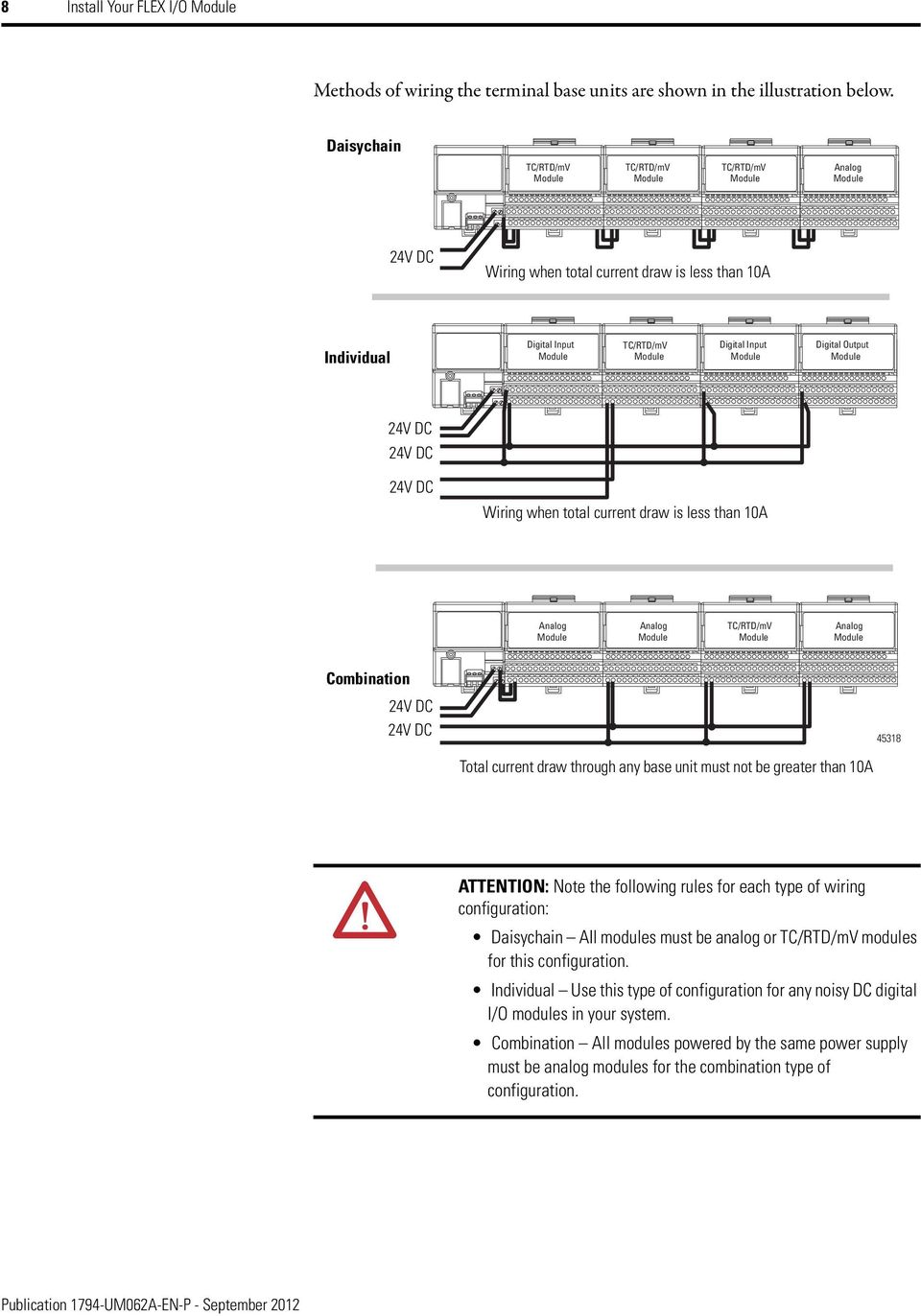
2-13 Chapter Summary. Connect individual output wiring to numbered terminals on the 0-15 row A as indicated in the table below 1794-OB8 - Terminals 0-7. Connecting Wiring for the Analog Modules.
The 1794-TB3 is used in an application with a 125V ACDC electrical rating and it has a maximum current capacity of 10A with 021 x 13 mm2 24-16 AWG stranded copper wire intended for use with input and output modules. Use only a soft dry anti-static cloth to wipe down equipment. The 1794-IB16XOB16P module mounts on a 1794-TB32 or -TB32S terminal base.
1794 FLEX IO Digital Modules. Connect Wiring Using a TB2 or TB3 Terminal Wire Connections for TB3G and TB3GS using the IE12 ModuleThe examples and diagrams in this manual are included solely for illustrative purposes. Or to the corresponding terminal on the 1633 row B.
Publication 1794-IN094D-EN-P - July 2018 European Hazardous Location Approval Approved for 1794-OB8 1794-OB8EP 1794-OB16 and 1794-OB16P modules. Connecting Wiring for the 1794-ID2 using a 1794-TB3 or 1794-TB3S terminal base unit 1. Each IO module requires a terminal base for connection points for IO wiring.
Publication 1794-IN094B-EN-P - April 2004 Connecting Wiring for the 1794-OB8 -OB8EP -OB8EPK -OB16 -OB16P and -OB16PK 1. Are Equipment Group II Equipment Category 3 and comply with the Essential Health and. The V AC common L2 terminals of row B and the odd numbered terminals of row A are internally connected together For 1794-TBN or 1794-TBNF.
1794-OB16 and -OB16PK - terminals 0-15. 2-13 Table of Contents. Connect individual outpu t wiring to numbered terminals on the 015 row A as indicated in the table below.
Connect Wiring for the 1794-IB8 -IB1 6 and -IB16K using a 1794-TB3 or -TB3S 1. Rotate the keyswitch 1 on the terminal base 2 clockwise to position 3 1794-IE12 4 1794-OE12 or 5 1794-IE8XOE4 as required. 2-8 Connecting Wiring using a 1794TB2 or TB3 Terminal Base Unit 2-9 Module Indicators.
1794-IF4I 1794-OF4I1794-IF2XOF2I1794-IF4IXT 1794-IF4ICFXT 1794-OF4IXT Analog IO Modules User Manual. Cover a wide electrical range. The following applies to products marked II 3 G.
If applicable connect the.
Flex I O High Density Analog Modules Pdf Free Download
Professional Allen Bradley 1794 Ob16p Flex 16 Pint Digital Output Module Supplier Allen Bradley 1794 Ob16p Flex 16 Pint Digital Output Module Manufacturer Amikonltd Com

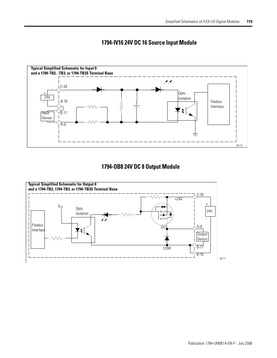
1794 Iv16 24v Dc 16 Source Input Module 1794 Ob8 24v Dc 8 Output Module Rockwell Automation 1794 Ob16d Flex I O Diagnostic Modules User Manual User Manual Page 121 132
Https Www Spectrumcontrols Com Media 1463 0100152 01 A0 Install Guide 1794sc If8iu Pdf
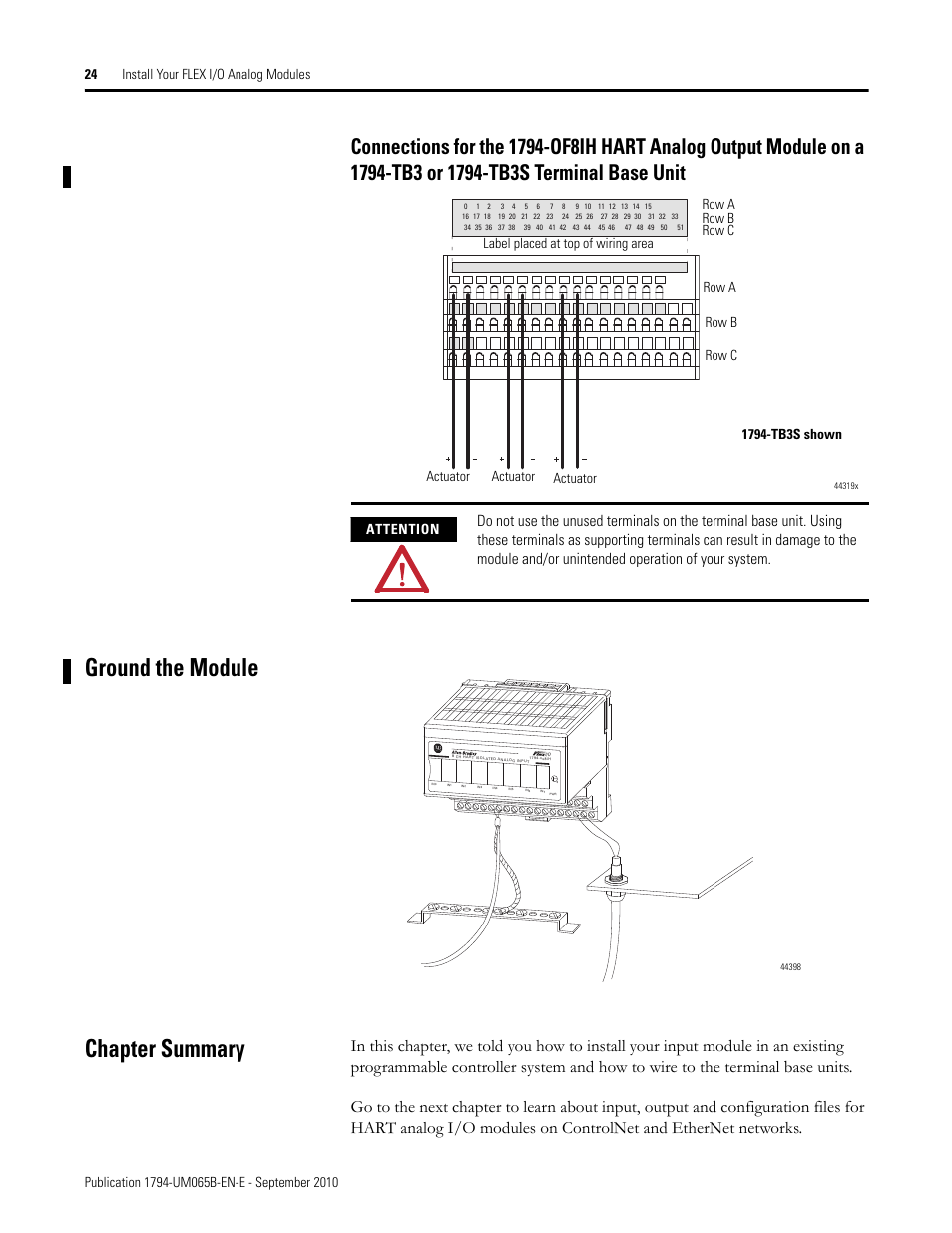
Ground The Module Chapter Summary On A 1794 Tb3 Or 1794 Tb3s Terminal Base Unit Rockwell Automation 1794 Of8ih Flex Isolated Input Output Hart Analog Modules User Manual Page 36 164
Rockwell Automation 1794 Ia8 Ia8i Ia16 Flex I O Ac Input Modules Installation Instructions User Manual Page 3 6

1794ib16 Ab Allen Bradley 1794 Ib16 Cbt Company
Flex I O High Density Analog Modules Pdf Free Download

Wiring Connections For 1794 If2xof2i Input Output Module Wiring Connections Rockwell Automation 1794 If2xof2i Flex I O 2 In 2 Out Isolated Analog Combo Module User Manual Page 3 6 Original Mode

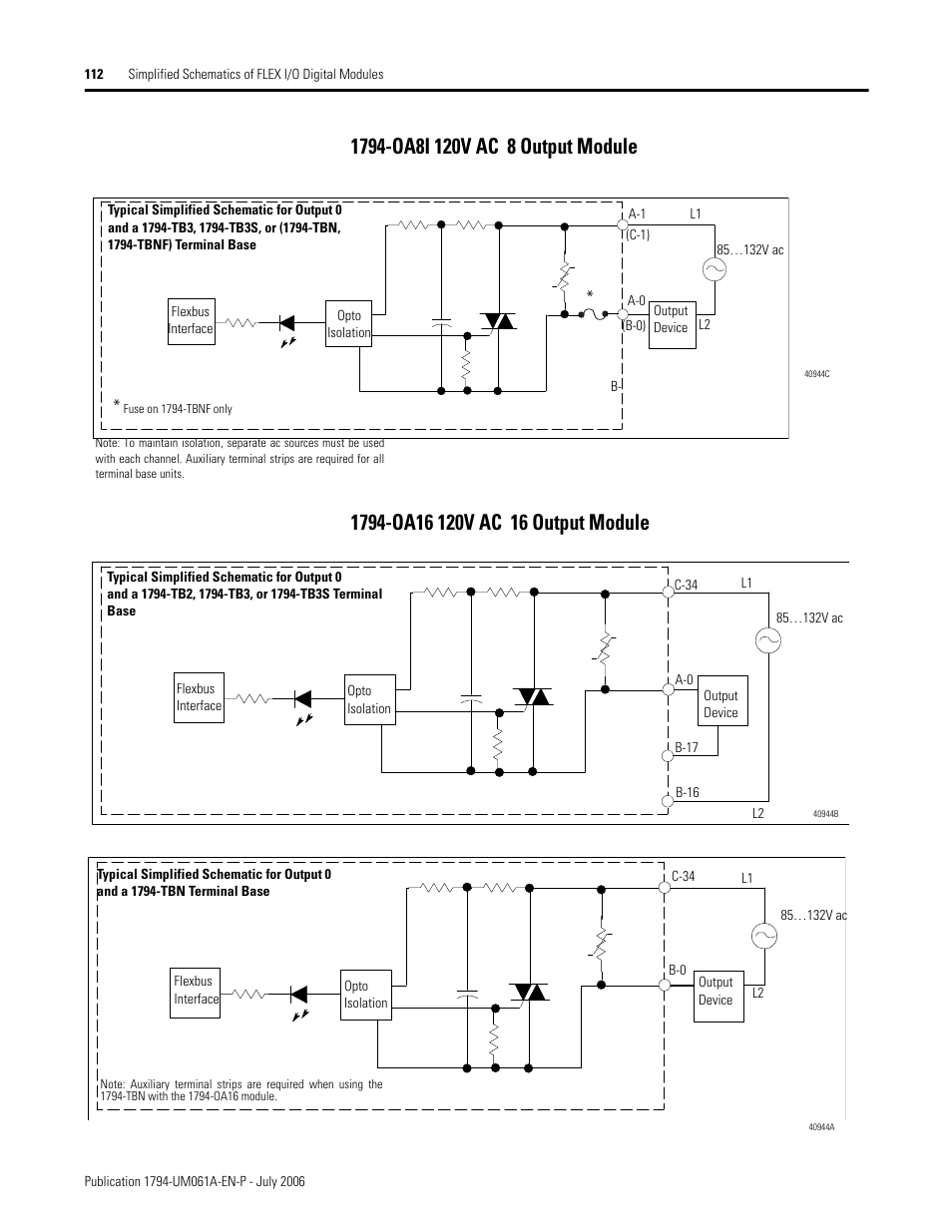
Connecting Wiring For The 1794 Oa8i Connecting Wiring For The 1794 Oa16 Rockwell Automation 1794 Oa8 Oa8k Oa8i Oa16 Flex I O Digital Ac Output Modules Installation Instructions User Manual Page 3 6
Https Www Spectrumcontrols Com Media 1463 0100152 01 A0 Install Guide 1794sc If8iu Pdf
Wiring Flex I O Analog Input Modules Rockwell Automation 1794 Flex I O System With Controllogix For Sil2 User Manual Page 31 60

Https Www Spectrumcontrols Com Media 1463 0100152 01 A0 Install Guide 1794sc If8iu Pdf
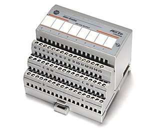
Plc Hardware Allen Bradley 1794 Tb3 Series A Used In Plch Packaging
Flex I O Digital Input Modules Pdf Free Download

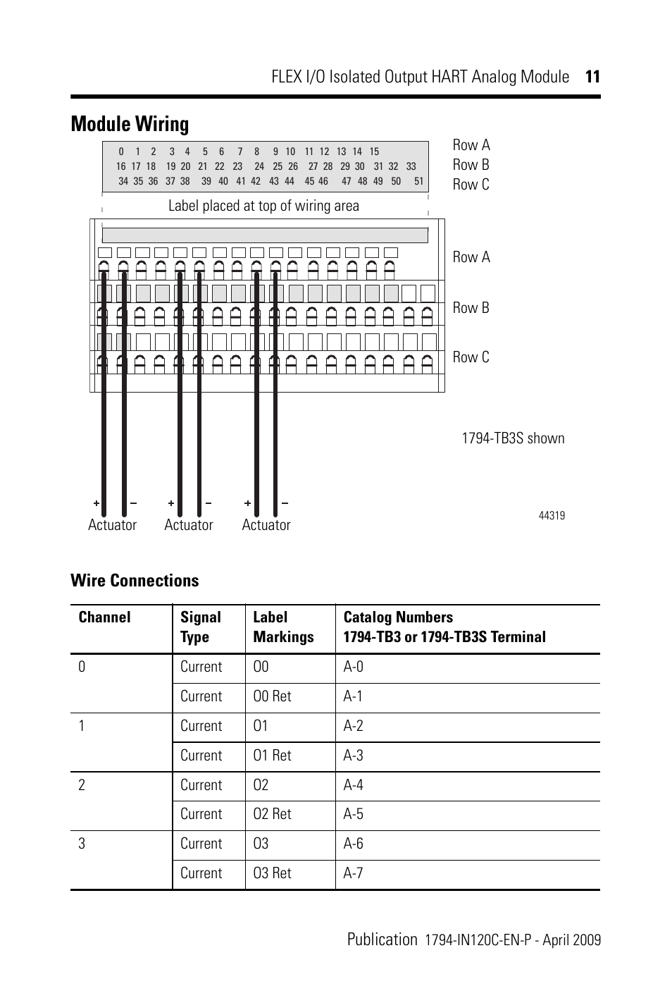
Module Wiring Wire Connections Rockwell Automation 1794 Of8ih Flex I 0 8 Isolated Output Analog Module User Manual Page 11 28
Flex I O Modules Allen Bradley United States
1794 Oa8i 120v Ac 8 Output Module 1794 Oa16 120v Ac 16 Output Module Rockwell Automation 1794 Ob16d Flex I O Diagnostic Modules User Manual User Manual Page 114 132
1794 Ow8 Flex Io Plcs Net Interactive Q A
